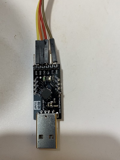
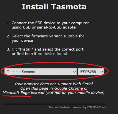
Tasmota

Installing

Follow Steps with these icons

SnifferBuddy

,

Smart Plugs for MistBuddy

,

SnapBuddy

,

Tasmota has enabled us to build low-cost sensor and camera devices that primarily use MQTT to transmit sensor readings. To date, GrowBuddies have implemented two ESP hardware configurations: the Wemos D1 ESP286 for sensor functionality and the ESP32-AI Thinker Cam for capturing time-lapse and streaming video.

Resources

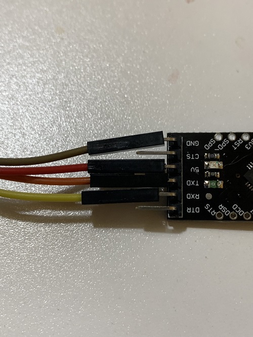
Wi-Fi module pinouts AI Thinker Tasmota Configuration documentation Tasmota ESP32-CAM Source Code

Before You Begin the Installation of a Sensor

Warning

Before installing a sensor, make sure that the sensor you want to use is included in the Tasmota binary. This is especially important for ESP286 devices, as they have limited storage space. Verify that your sensor is included before starting the installation process.

Two ways to check if the sensor is in the Tasmota Build (I’d check both):

Check the Documentation

To check if a sensor is supported by Tasmota, visit the BUILDS documentation and refer to the table. In the “t” column, you can find information about which sensors are included in the builds for the ESP286 and ESP32 chips. An “x” in the cell indicates that the sensor code is included in the build. For example, searching for the SCD40 sensor will show that the “t” entry has “-/x”, meaning that the SCD40 sensor code is not included in the ESP286 build but is included in the ESP32 build. If you want to add support for a sensor that is not currently supported, you can follow the instructions in the Compiling using GitPod guide.

Check from the Console

If you have installed Tasmota, you can verify if you have wired the I2C sensor correctly with the i2cscan Tasmota console command. To check if the driver for the sensor is loaded in the Tasmota build, execute i2cdriver from the Tasmota console.

Web Install Tasmota

Note: Web install does not work with the AI Thinker ESP32-CAM. To web install Tasmota, use either the Edge or Chrome web browser (the web install method does not work with Brave). Navigate to the Tasmota Install URL. The first thing the Tasmota install will want to do is connect to the ESP.

Wemos D1 USB Connectivity

Connecting microcontrollers to PCs is often not as simple as “plug-and-play.” If your PC is having trouble identifying the USB/COM port, try the following steps:

  • Verify that the cable supports data input and output. Many USB cables are intended for power delivery only and may not support data transfer.

  • Check if the CH340/CH341 driver is installed and functioning properly. The driver is essential for the PC to communicate with the microcontroller through the USB-to-serial adapter.

SnapBuddy USB Connectivy

The AI Thinker ESP32 does not have native USB support. We need to use an FTDI USB to Serial adapter board like the one linked here to translate the RS232 serial communication into a format that our computer can understand.

Set Up Windows Drivers

Assuming you are on a Windows 10 PC (I say this because it is what I am running), follow the steps outlined in Darren Robinson’s article, ESP32 Com Port – CP2102 USB to UART Bridge Controller.

Connect the FTDI <-> ESP32-CAM

Here’s the FTDI adapter board I used. There are many different boards available. The setup should be the same.

_images/ftdiSerialToUSB.jpeg

FTDI Adapter Board

and

_images/FTDI_board_pins.jpg

FTDI Adapter Board

Here’s how the wiring looks from the ESP32:

_images/AIThinker-pinout.jpg

AI Thinker Cam Pinout

FTDI Wiring to AI Thinker Wiring

wire color

FTDI pin

ESP32-CAM pin

yellow

RXD

U0T

orange or green

TXD

U0R

red

5V

5V

black

GND

GND

The ESP32-CAM can be configured in two ways:

  • Flash mode: To upload code, connect a wire between the GPIO0 and GND pins. The chip must be grounded through the GPIO0 pin to indicate that code is being uploaded.

  • Execution mode: In this state, the GPIO0 pin is not connected to GND (i.e.: the wire can be removed).

For the next step, put the ESP32-CAM into Flash mode.

Flashing Tasmota onto the ESP32-CAM

A web install of Tasmota onto the AI Thinker ESP32-CAM kept failing.

I was far more successful installing Tasmota on the AI Thinker using Jason2866’s ESP flasher.

  • Download the version for your computer (e.g.: I download ESP-Flasher-x86.exe), install locally.

  • Connect the FTDI cable as well as the wire to put the ESP32 into the bootloader state.

  • Follow the instructions on the UI.

AI Thinker’s ESP32-CAM uses an ESP32-S chip. There is no support for USB. To connect the ESP32-CAM to a USB Port AMAZING -> https://cgomesu.com/blog/Esp32cam-tasmota-webcam-server/#installation {“NAME”:”AITHINKER CAM”,”GPIO”:[4992,1,672,1,416,5088,1,1,1,6720,736,704,1,1,5089,5090,0,5091,5184,5152,0,5120,5024,5056,0,0,0,0,4928,576,5094,5095,5092,0,0,5093],”FLAG”:0,”BASE”:2}

esptool.py --port COM5 erase_flash

esptool.exe --port COM5 write_flash -fs 1MB -fm dout 0x0 tasmota32-webcam.bin

https://github.com/Jason2866/ESP_Flasher/releases - ESP Flasher - use this, put in the pics….

commands from https://cgomesu.com/blog/Esp32cam-tasmota-webcam-server/#installation

Semsors

Install the Tasnmota Sensors binary for the ESP286 if the sensor is included by default in the Sensors build (see before installation).

_images/install_tasmota.jpg

Tasmota Web Install

Connect to WiFi

The installation includes connecting to the home wifi.

If you want to be sure the ESP286 has been “Tasmotized” correctly, you can use a tool like Angry IP to show the IP address.

_images/angry_ip_tasmota.jpg

Angry IP Scan Shows Tasmota

Choose your adventure for the rest of install:

Restore Config File

Choose Restore Configuration

_images/tasmota_restore.jpg

Restore Configuration UI

Tasmota config files have the .dmp extension. The backup config file is:

  • /bin/Config_snifferbuddy_11.1.0.1.dmp for SnifferBuddy.

  • /bin/Config_mistBuddy_fan_10.1.0.dmp for the Tasmotized plug designated for mistBuddy’s fan.

  • /bin/Config_mistBuddy_mister_10.1.0.dmp for the Tasmotized plug designated for mistBuddy’s mister Power Supply.

Choose the file for the component you are building and start the restore.

Install Without Config File

Now Visit the Device. Go into Configure Module and choose:

  • if you are building a sensor like SnifferBuddy, choose Generic(18) and then Save.

  • if you are building a Tasmotized Sonoff plug, choose

Configure Host Name

I like to configure the Host Name as soon as possible so I can get to the device with a name.

_images/tasmota_wifi_snifferbuddy.jpg

SnifferBuddy Host Name

Here I chose the name SnifferBuddy-SCD40 to note this is a SnifferBuddy using the SCD40 sensor. Click on Save. Wait for the Main Menu to come back.

Configure GPIO pins

Go back into Configure, and choose Configure Module. From here set up the GPIO pins as shown in the image below.

_images/tasmota_config_gpio_pins.jpg

Tasmota Setting GPIO pins

Configure mqtt

Go to Configure MQTT.

  • Set the Host to growBuddy (assuming the mqtt broker is named growBuddy).

  • Set the topic to the Buddy being enabled (in this case SnifferBuddy).

  • Change the prefix part of the Full Topic to start with growBuddy.

_images/tasmota_mqtt_config.jpg

Tasmota mqtt Settings

Save and go back to the main menu.

Check mqtt

Using a tool like MQTT Explorer

_images/tasmota_mqtt_explorer.jpg

MQTT Explorer

We see in the image that the sensor reading for the photoresistor (A0) is available. The value is 585. The SCD40 values are not there. This is because as noted in the section Before You Begin Installation, the SCD40 is not a part of the ESP286 sensors build. The driver needs to be added separately as discussed above.

Commands

Tasmota supports A LOT of commands. The ones listed below were used on Tasmotized Buddies (like snifferBuddy). Commands are accessed by clicking on the Console button in the main menu.

_images/tasmota_main_screen.jpg

Tasmota main menu

The main menu is then replaced with the console where commands can be entered.

_images/tasmota_console.jpg

Tasmota main menu

Set Time Between Readings

Set up the period between sending the sensor readings over mqtt using the teleperiod command. e.g.:

teleperiod 60

sets sending readings via mqtt to occur every minute.

set Local Time

This command set the correct timezone stuff for PST:

Use the web console to configure the Timezone (this shows Pacific time):

Backlog Timezone 99 ; TimeDST 0,2,03,1,3,-420 ; TimeSTD 0,1,11,1,2,-480

The 99 says to use TimeDST and TimeSTD. Use “time” to check.

Thank you Craig’s Tasmota page

Or Keep It Simple and just change the timezone with the command timezone -8 (see Tasmota commands

Set Temperature Readings to F or C

Typing in the command without an option returns the current setting.

21:45:11.776 CMD: setoption8
21:45:11.782 MQT: growBuddy/snifferbuddy/RESULT = {"SetOption8":"ON"}

Weirdly, “ON” means temperature readings will be in Fahrenheit.

21:46:30.756 CMD: so8 0
21:46:30.761 MQT: growBuddy/snifferbuddy/RESULT = {"SetOption8":"OFF"}

The temperature is set to celsius with the command so8 0. To Fahrenheit with the command so8 1.

Accomodate SCD30 Slow To Discover

The first time I used the SCD30 with Tasmota on a Wemos D1, it didn’t work. The reason is discussed below. SetOption46 was added in Tasmota 12.1.1. SetOption46 0..255 stalls I2C component discovery for 0..255 * 10 milliseconds to let stabilize the local Wemos power. You might want to experiment with values like SO46 10 or SO46 20 for a 100mSec or 200mSec delay.

Commands To Verify the Install

Two commands, i2cscan and i2cdevice are extremely helpful in determining if the software and wiring are correct.

i2cscan

i2cscan is an extremely useful command. Executing i2cscan from the console is useful to show you if the i2c sensor is wired correctly. It is useful right after an installation to see if the wiring to the ESP286 is correct.

21:41:54.158 CMD: i2cscan
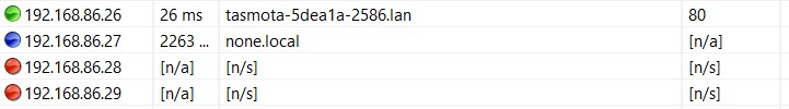
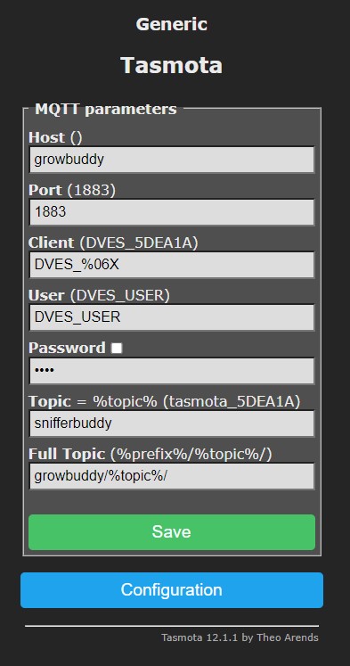
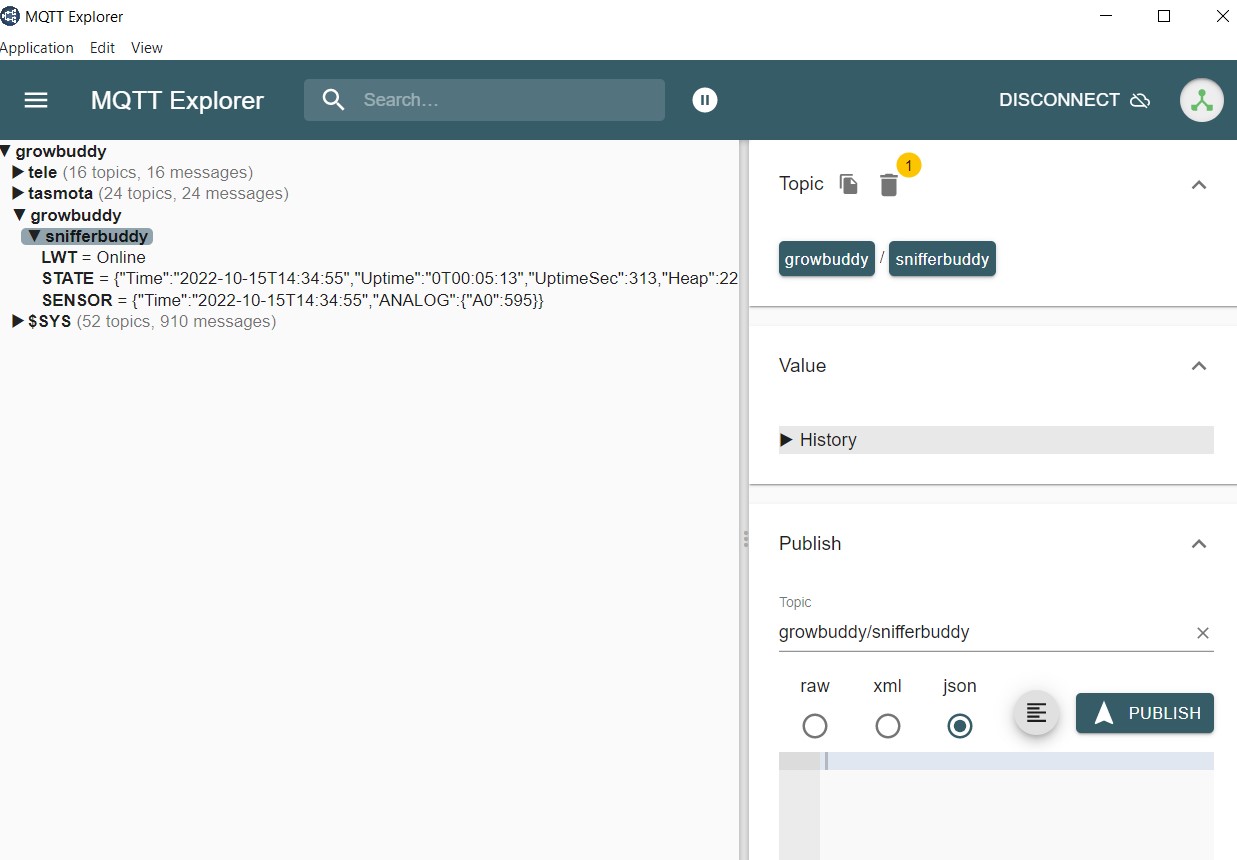
21:41:54.179 MQT: growBuddy/snifferbuddy/RESULT = {"I2CScan":"Device(s) found at 0x62"}

The above is a verification that the wiring works for the ESP286/SCD40 I built since 0x62 is the SCD40’s I2C address.

i2cdriver

i2cdriver shows the list of drivers that were loaded by the Tasmota build. For example, by default, the SCD40 is not in the ESP286 Tasmota Sensors build. This is shown in Tasmota’s build table.

_images/scd_in_builds.jpg

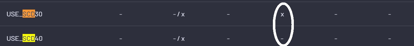
I find the builds table challenging to read. Here’s my take:

  • The rows are for each sensor where there is a Tasmota driver.

  • The s column is for sensors. I’m guessing (this is not obvious to me) the X (Sensor included) and - (Sensor not in build) in this column is referencing the ESP286 Tasmota sensors build.

  • The t column is for ESP286/ESP386 Tasmota build. This column says the SCD30 and SCD40 are in the ESP32 Tasmota build - so I assume also in the ESP32 Sensor build since it is a subset.

21:40:49.852 CMD: i2cdriver
21:40:49.861 MQT: growBuddy/snifferbuddy/RESULT = {"I2CDriver":"7,8,9,10,11,12,13,14,15,17,18,20,24,29,31,36,41,42,44,46,48,62"}

From the results of i2cdriver, I can see the SCD40 (which sits on i2c address 0x62) is in this build. I created a custom build in order to include the SCD40 in the set of software drivers shown by i2cdriver.

Switchmode

The Tasmota command switchmode commands Tasmota to send an mqtt message when there is a change in state. This command came in handy when I had an actuator that just needed on/off (like a power switch as the name implies).

switchmode1 15
switchmode2 15

Compile Tasmota with GitPod

To add a sensor to the build or debug, you’ll want to get into VS Code and play around with the code.

_images/tasmota_build_output.jpg

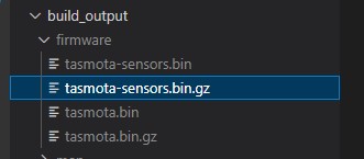
Tasmota Sensors Build Location

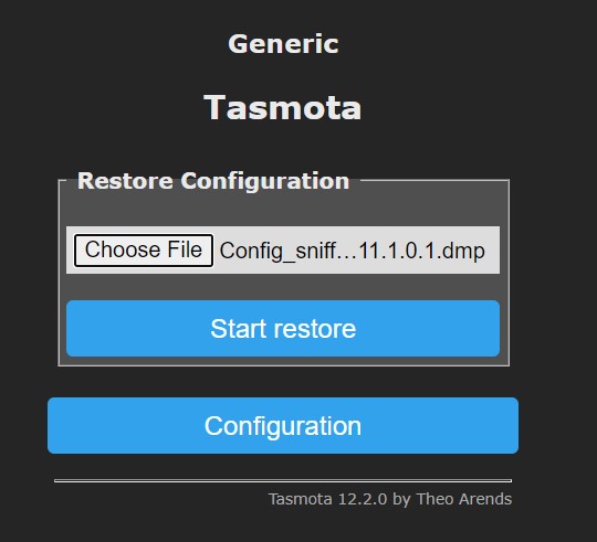
  • Go to the main Tasmota screen and select Firmware Upgrade.

  • Upload the sensor binary and click on Start Upgrade.

Flash Tasmota Onto a Sonoff Plug

We need a way to turn a plug on or off. For example, MistBuddy uses two Tasmotized plugs. One turns MistBuddy’s fan on and off. The other turns MistBuddy’s mister on and off. By Tasmotizing the plugs, other Buddies can send mqtt messages to turn a plug on or off.

The Sonoff S31 (or S31 Lite) can be flashed so that Tasmota is running on our local network. This YouTube video gives instructions on how to flash Tosmota.

ooh! Extra care when soldering. If not, well…it is way too easy to rip off one of the pads…

Once flashed and rebooted:

  • Put the plug back together.

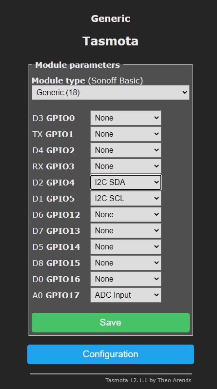
  • Set the Module type to Sonoff S31.

_images/Tasmota_S31_Config.jpg

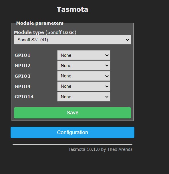
Tasmota Sonoff Configuration

Use the Tasmota S31 configuration when you go through the Tasmota install

Adding a Sensor Driver

ESP286/SCD30 Modifications

I added this section to maintain what I learned with the Wemos D1 + SCD30 Setup

I fixed a problem with the SCD30 + ESP286 (Wemos D1) not working without a restart. I couldn’t get the Tasmota team to look at it at the time it happened so I fixed it and submitted a PR. A bit later on, another person had the same challenge. Wonderfully, arendst pointed out From the datasheet it needs 2 seconds to power up. The current code doesn’t allow this. (see PR 15438). This may be unique to the Wemos mini D1 ESP286 (noisy power…?).

After further investigating the Wemos D1 powering and communication with the SCD 30, Arends notes: As I thought. The Wemos D1 is flakey at power on. (That’s what $1.50 buys us!). In latest dev there is a new command called SetOption46 0..255 allowing you to stall initialization for 0..255 * 10 milliseconds to let stabilize the local Wemos power. You might want to experiment with values like SO46 10 os SO46 20 for a 100mSec or 200mSec delay. If you own the Adafruit SCD30 you might also want to power the device from 5V as it draws a lot of power when measuring (notice the fainting power led because the wemos LDO just cannot provide enough power for the device. YMMV.

I have not had a challenge running on 3.3V. Obviously, Arendst knows ALOT so his advice should be kept in mind.

The SetOptions46 is avalailable in Tasmota 12.1.1

The files I modified include:

  • xsns_42_scd30.ino. From what I can tell, Tasmota started as an Arduino project. The interface into (3rd party) sensor code is a .ino file like this one for the scd30. The current code:

void Scd30Detect(void)
{
  if (!I2cSetDevice(SCD30_ADDRESS)) { return; }

  scd30.begin();

On the ESP2866 Wemos, the code doesn’t get past the initial if statement in the scenario when the ESP8266 is powered up. It does pass when restarting with restart 1 on the command line. Most likely, powering up is taking longer on the ESP286 to the point Tasmota is impatient and doesn’t wait for the scd30 to be powered up. I did not debug further to find out how to robustly fix it. I got to a build that “works for me” with simply:

void Scd30Detect(void)
{
#ifdef ESP32
  if (!I2cSetDevice(SCD30_ADDRESS)) { return; }
#endif
  scd30.begin();
#define TEMP_CONVERSION        false             // [SetOption8] Return temperature in (false = Celsius or true = Fahrenheit)

to true to show temperature readings in celsius. As the comment states, I could have set this on the command line using SetOption8 1.