SnifferBuddy
About
SnifferBuddy is a device that measures the temperature, humidity, and CO2 level of the air using an SCD30 or SCD40 sensor. It is controlled by an ESP286 microcontroller - a Wemos D1 - running Tasmota firmware, which publishes the readings to an MQTT broker.
Supported Sensors
SnifferBuddy’s sensors were chosen for their accurate CO2 readings, price, and ease of use. Initially, Buddies use temperature and humidity readings. Eventually, we will also monitor and adjust CO2 levels, but first, we need to optimize the grow area for proper water distribution in the air and soil.
The SCD-30 and SCD-40 sensors are currently supported. I initially used the SCD-30, but later switched to the SCD-40 because it is more affordable and smaller in size, yet still of high quality.

A Happy SnifferBuddy with an SCD-30 Sensor hanging about
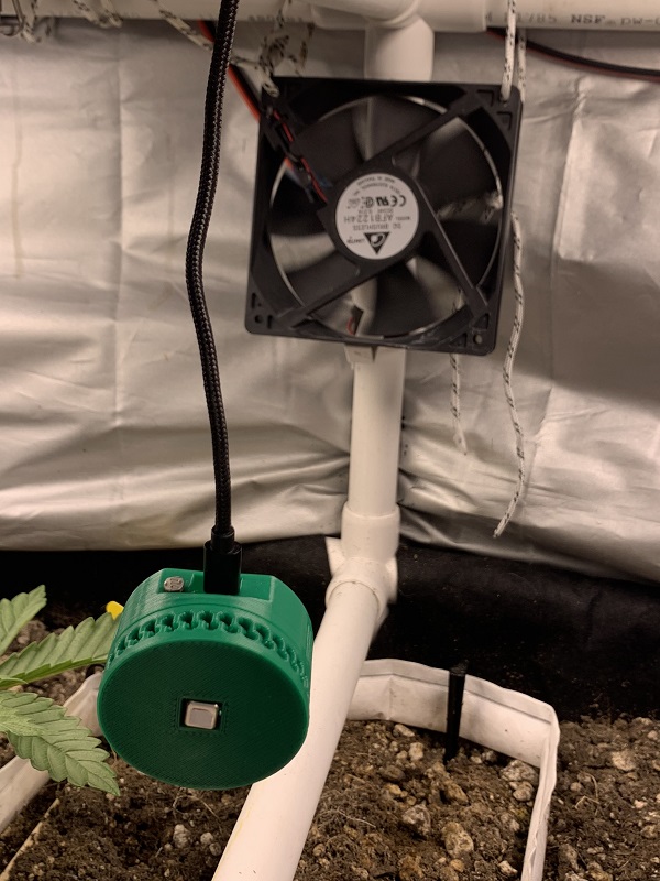
A Happy SnifferBuddy with an SCD-40 Sensor hanging about
Let’s Make One
Note
SnifferBuddy sends out MQTT messages containing sensor readings as the payload. It can be used in any MQTT environment. If you have set up Gus, it will be able to handle the messages sent by SnifferBuddy. This document assumes that you have already built Gus.
Gather The Materials
SCD30 sensor or SCD40 sensor component.
Warning
The SCD40 driver is not included by default in the Tasmota sensor build for the ESP286. I compiled a Tasmota sensor build that includes the SCD40. There will also be different Tasmota installation steps.
ESP8286 component.
Photoresistor and 10K through hole resistor. I had a lot of these kicking around. I bought something similar to this kit.
3D printer and PLA filament for printing out the enclosure.
Superglue for gluing the top Wemos part of the enclosure to the cap part of the enclosure.
USB cord and plug the ESP8286 to power.
4 4mm M2.5 or M3 bolts.
Make the Enclosure
Enclosures are made in Fusion 360 and printed on a Prusa MK3S printer.
SCD-30
Directory containing scd-30 enclosure files
To make the enclosure, download and print the 4 mesh files.
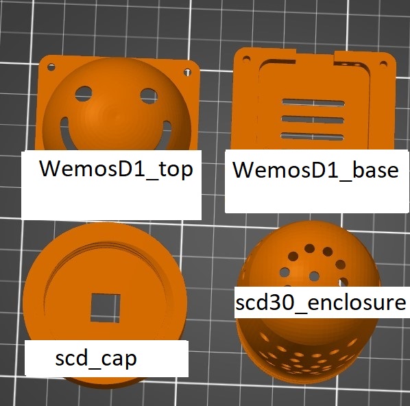
SnifferBuddy Enclosure Parts
I use the F360 app extension Parameter I/O while modeling to import/export the parameters found in SnifferBuddyParams.csv.
SCD-40
Note
Thank you, sumpfing, for your modular Wemos D1 design.
Directory containing scd-40 enclosure files
The SCD-40 I built is made of two rings as shown in the image:
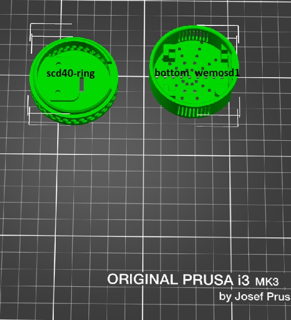
SCD-40 Ring Design
Moving forward, I will use a third ring for the photoresistor and put it between the bottom and scd-40 ring.
Wire the Components Together
Wiring is the hardest part.

SCD-40 Wired Up
Photoresistor
Wemos D1 ESP286
SCD-40
Note
The images show that the photoresistor was placed in the bottom ring near the USB port opening. However, this causes interference between the wires and the placement of the ESP286 in the bottom ring. In future builds, I will use a ring similar to the one used for the SCD-40 to eliminate this interference.
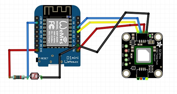
SnifferBuddy SCD-40 Wiring
I decided to use the ESP826 chip and Tasmota firmware for the SnifferBuddy because Tasmota was specifically designed to provide MQTT and OTA functionality for ESP8266-based ITEAD Sonokff devices. While I did encounter an issue with the Wemos D1 ESP286 when I was building the first SnifferBuddy, the ESP826 has proven to be an inexpensive and reliable choice. I ordered a bunch of ESP286s from Aliexpress. To further enhance the SnifferBuddy’s capabilities, I also added a photoresistor to the top of the device. This allows me to determine whether the grow lights are on or off, which helps me to provide the appropriate daytime or nighttime care for my plants.
I used a wired 4-pin JST SH connector to connect the Wemos D1 to the SCD sensor. The wiring process can be challenging, so I summarized my thoughts on it in a separate document. By soldering the SDA, SCL, 5V+, and GND lines to the Wemos D1 pins, I was able to establish connectivity for the I2C lines of the SCD-40. In addition, I wired up the photoresistor, although I should have used another ring for this.
To measure the voltage of the photoresistor, I used a voltage divider circuit. This allows me to determine whether the LED lights are on or off, which is important for knowing when to perform certain activities, such as adding humidity, during the day or at night. A pull-up resistor with a resistance value of 10K completes the circuit.
Install Tasmota
Time to install Tasmota onto the ESP8286. See Tasmota Installation.
Verify Install
You can use a tool like mqtt explorer to see if SnifferBuddy is sending out mqtt messages.

Time to (HOPEFULLY) Celebrate.
Let’s Use One
SnifferBuddy publishes temperature, humidity, and CO2 level readings to an MQTT broker, making it suitable for use in any environment that can subscribe to MQTT messages. This allows SnifferBuddy to be easily integrated into a variety of systems and settings.
Gus is an integral part of the GrowBuddies system. If you choose to build Gus, you will be able to use Gus to store and visualize SnifferBuddy’s readings, including the calculated vapor pressure deficit (VPD) value. This allows you to easily track and analyze the environmental conditions in your grow area, helping you to optimize your plants’ growth and health.